
XS Plastic Mould Co., Ltd have long history in making stretch blow moulds for the semi-auto and full-auto stretch blow molding machine. Blow moulds play a large part in making high-quality bottles. While the machine has to deliver preforms at the right temperature, it is the blow moulds that give containers repeatable features and a brilliant appearance.
- Bottle design
Before stretch blow mould design, we need to make bottle design and confirm with client first.


XS Plastic Mould Co., Ltd provide both 2D and 3D bottle drawing. We make the drawing according client’s bottle sample or pictures. We can make the little change on the design according customer’s requirement.
- Strech blow mold design

Today’s mold-making process starts with a three-dimensional (3D) computer model of the container itself. Physical models may be made by a variety of processes, the most popular still being stereo lithography with 3D printing catching up quickly because of the availability of low-cost printers. The model may be used to give marketing people a better “feeling” for a new container. Once approved, data of the computer model are then fitted in a new or existing mold base. At this point, shrinkage has to be added to the container dimensions. Polyethylene terephthalate (PET) shrinks approximately 0.08% but shrinkage is not uniform and it is the experience of the mold maker that determines how closely the capacity of the container matches specification. A variety of computer-aided design (CAD)/ computer-aided manufacture (CAM) programs allow the creation of machine cutter paths that are downloaded directly into high-speed machining centers. Machine operators load and center blocks of aluminum of suitable size and special cutters, spinning at up to 30,000 r.p.m., move at a speed of up to 20 m/min. The resulting cavity surface is already smooth to the eye but most mold makers add a high, mirror-like polish, which still requires skilled, manual labor. The use of sandblasted surfaces that are common in other plastic processes has gained some ground as there is little difference in the appearance of the containers. Some mold makers then coat the cavity surfaces with various materials, often containing nickel and Teflon, to give it abrasion resistance.
Neck and thread finish are already formed in the preform; so blow molds form only the body and base of the bottle. In the reheat stretch blow molding (RSBM) process they consist of three parts: two mold halves and one base insert (also called push-up). The base insert is necessary because the walls at the base of the concave container could not slide over the mold halves during mold opening if these were forming them. Instead, the verti-cally moving base insert is drawn out of the way before, or as, the mold opens. While the three-piece design is common to all molds, they are manu-factured quite differently depending on the type of machine to which they will be fitted. Linear machines have all mold cavities mounted within two blocks where the cavities sit side by side. In rotary machines each blow mold is mounted to a separate carrier, opening and closing individu-ally. Modern machines use so-called shell molds whereby the actual mold halves are only 5-mm thick and are assembled onto bases that are all the same for a family of containers. These bases carry all water connections and need not be touched during a changeover, thus reducing valuable time.
- Stretch blow mould material


Normally use Aluminum 7075, steel P20 or steel C45 to make the stretch blow moulds. Quality and price 7075 > P20 > C45. Base inserts may be of the same material or made from beryllium–copper. Aluminum 7075 especial high heat
transfer rate, easy machinability, and lightweight. Most of the full automatical stretch blow molding machine moulds widely use aluminum 7075 to make the moulds.
- Venting


Venting is another area where the experience of the mold maker becomes extremely important. Because PET fills the mold cavity during blowing, the air inside the cavity must be exhausted. For this purpose mold makers add a variety of vents. Compared to other processes, such as injection molding or extrusion blow molding, PET is processed at a relatively low temperature in the RSBM process. Vent sizes are limited to 0.04 mm (0.0015 in.) in injection molding but vents of up to 0.5 mm (0.020 in.) are used in RSBM with hole vents up to 1 mm (0.040 in.). All molds have vents on the contact surface of the cavities. One mold half is typically completely recessed against the mold base by up to 0.20 mm (0.08 in.) or more commonly by 0.15 mm (0.006 in.). Base vents are also common and are accomplished by leaving the base insert to move 0.25–0.3 mm (0.010–0.012 in.) downward under the force of the stretch rod. The resulting ring-shaped gap between base insert and mold cavity allows air to escape. Hole vents up to 1 mm are used in areas where air entrapment is suspected. Vents of this diameter may not show in areas where the material has stretched and consequentially strain-hardened but will show as small dimples where this is not the case. A common example of highly stretched material is the foot of a petaloid base for carbonated soft drinks (CSD) containers. Two small holes in each foot let air escape that might otherwise be trapped by the material flowing around it. Another use of venting is to direct PET into hard-to-blow areas. In a highly oval bottle, for example, there is always the possibility of a ridge of higher wall thickness forming at the center of the narrow side of the container. Vent holes at the far side of the mold can attract PET to flow more quickly into these areas, thereby stretching out the preform walls close to the narrow side. A fine sandblast finish instead of the mirror-finish also helps to let the air move out of the mold. Due to low temperature in the RSBM process compared with uses in other processes, PET does not flow easily into small mold crevices. Minimum dimensions for female radii might be given as 0.8 mm (1/32 in.) but it will depend on the stretch ratio of the PET flowing toward it whether it will fill out or form a greater radius instead. Male radii should be double that amount especially when used in bases. Here a sharp radius may cause a crease in the material and open the door to stress cracking. Venting in these areas can be attempted to reduce the risk of air entrapment stopping the advance of the parison but more often than not they do not seem to have much effect. We will simply have to live with the fact that PET benefits from more generous radii in this process.
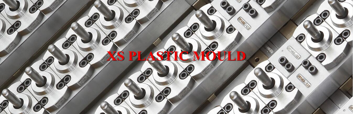
- Stretch blow mold pictures


- Stretch blow mould test video
• Stretch blow mould for full automatic stretch blow moulding machine in our workshop.